+372 62 28 220 call us for best offer


- Home
- Products
-
 Frequency inverters
-

- Advanced Control compact C220 series
- Advanced Control C420 compact series VFD
- Advanced Control M420 multi-purpose series VFD
- Advanced Control M430 multi-purpose series Drives
-

- FVR Micro Drives (FVR AS1) economical series for basic applications
- FRENIC Mini Drives (FRN C2) compact series for general purpose
- FRENIC Ace Drives (FRN E2) multi use series for general purpose
- FRENIC AQUA Drives (FRN AQ1) series for pumps and water supply
- FRENIC HVAC Drives (FRN AR1) series for heating, ventilation and air-conditioning
- FRENIC Mega Drives - (FRN G1) series for general purpose
- FRENIC Lift Drives (FRN LM1) series for lift and hoisting applications
- FRENIC Lift Drives (FRN LM2) series for lift and hoisting applications
- FRENIC-VG Drives (FRN VG1) versatile series for heavy duty industrial applications
- FVR Micro Drives (FVR S1) economical series for basic applications
- Fuji FRENIC Mini Drives (FRN C1) compact series for general purpose
- FRENIC-Eco (FRN F1) series for pumps and HVAC
- FRENIC Multi Drives (FRN E1) series for general purpose applications
-

- Hitachi Drives NE-S1 economical compact series for basic applications
- Hitachi Drives WJ200 compact series for general purpose applications
- Hitachi Drives WL200 small versatile series for general purpose applications
- Hitachi Drives SJ700B high performance series for pump applications
- Hitachi Drives SJ700D high performance series for general purpose use
- Hitachi Drives SJ-P1 cutting edge series for general purpose applications
- Hitachi Drives X200 compact series for general purpose applications
- Hitachi Drives SJ700 power series for general purpose
-
-
 Medium-voltage frequency inverters
-
 Servo systems
-
 Soft starters
-
_series.png) PETER ELECTRONIC SAS (3kW~11kW) series
PETER ELECTRONIC SAS (3kW~11kW) series -
_series.png) PETER Electronic VersiStart II (3,5A~16A) series
PETER Electronic VersiStart II (3,5A~16A) series -
_series.png) PETER Electronic VersiStart II (17A~45A) series
PETER Electronic VersiStart II (17A~45A) series -
_series.png) PETER ELECTRONIC VERSISTART P II (24~229A) series
PETER ELECTRONIC VERSISTART P II (24~229A) series -
_series.png) PETER Electronic VersiStart III (9A~45A) series
PETER Electronic VersiStart III (9A~45A) series -
_series.png) PETER Electronic VERSISTART P III (24~580A) series
PETER Electronic VERSISTART P III (24~580A) series -
_soft_starters.png) PETER Electronic VERSICOMB II SAFE (12~60A) series
PETER Electronic VERSICOMB II SAFE (12~60A) series
-
-
 Braking devices
-
 Relays and monitoring devices
-

- Emergency stop modules
- Safety gate monitoring
- Light barriere controlers
- Two-hand control modules
- Safety mat modules
- Extension / delay time / interface modules
- Standstill and speed monitors
- Multifunctional safety solutions
- Wireless Safety
-

- Insulation monitors
- Equipment for insulation fault location
- Residual current monitors
- Measuring relays
- Fault annunciators
-

- Semiconductor relays- contactors
- Softstarters
- Motor brake relays
- Reversing contactors
- Speed controller
- Multifunctional motor control untis
-

- Timers
- Interface / Switching relays
- Power supply units
- CANopen PLC
- CANopen I/O modules
-
- Remote control switches
- Specific installtion devices
- Time switches MINITIMER
-
-
 PRESSURE AND LEVEL TRANSMITTERS
-
 PRESSURE TRANSMITTERS FCX-AII V5 SERIES
 -
 High static pressure differential transmitters for Oil & Gas applications
 -
 Pressure transmitters for nuclear applications
 -
 Pressure transmitters Specific Pressure Transmitters series
 -
 Pressure transducers
 -
 Accessories for pressure transmitters and differential pressure devices for flow measurement
 -
 hydrostatic pressure transmitters
-
-
 FLOW AND ENERGYMETERS
-
 ENVIRONMENT AND GAS ANALYZERS
-
 Exhaust gas monitoring NOx converter - ZDL
 -
 ATEX in-situ oxygen analyzers
 -
 Paramagnetic Oxygen Analyzer - ZAJ
 -
 NDIR CO2 Controller
 -
 In-situ zirconia oxygen analyzers
 -
 Cross Stack Laser Gas TDL Analyzer - ZSS
 -
 Infrared gas analyzers ZRE ZKJ ZPA ZPB ZPG
 -
 ZFDM-4 Dust Monitor
 -
 Hydrogen Analyzers Thermal Conductivity Gas Analyzer - ZAF4
 -
 Flue gas humidity meter - DELTA O2
 -
 Fuji ZMV Microventuri flue gas flowmeter
 -
 Portable NDIR analyzer & sample conditioning system - ZSVS / ZSVF
 -
 Fuji CEMS Software Suite
 -
 S-Keeper 7TM
 -
 Modular analysis system for on-board continuous emissions monitoring
 -
 ZPAF Biogas Analyzer & ZPSB Biogas Analysis System
 -
 Portable Neutron Survey Meter NSN3
 -
 Electronic Personal Dosimeter NRF50
-
-
 HMI Panels
-
 MONITORING AND DATA ACQUISITION
-
 Process Controllers
-
 Digital panel meters FD3000, FD6000, FD9000, FXE, FXEI, FXE-B & FXEI-B
 -
 Process controllers PXH series
 -
 Process controllers PUM series
 -
 PXF series - Digital temperature controller
 -
 Multi-function PID controller - PSC series
 -
 Control pack to control, record and program
 -
 Static relays
 -
 Thyristor Power Controller
 -
 Process controllers FRC series
 -
 Wireless temperature HUB WGATE-POD-EMS
 -
 Signal processing Temperature transmitters
 -
 Temperature sensor - PT100
 -
 Thermocouples
-
-
- About
- News
- Downloads
- Service
- Contacts


.png)


DOLD Reversing contactors POWERSWITCH

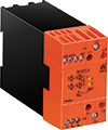
DOLD reversing contactors of the POWERSWITCH series are used to change the direction of rotation in alternating current motors, start them gently and/or to monitor their load. Various diagnostic functions inform you constantly about the operating condition of the motor. The DOLD reversing contactors save space and have few wires as all functions are combined in a single housing. Costs can also be saved as an alternative to a frequency converter. The devices are universally usable, e.g. for extruders, pumps, actuators or conveyors.


| Type | Function | Load current [A], 3 pole | Load voltage, 3-phase AC [V] | Auxiliary voltage AC [V] | Digital triggering [V] | Temperature monitoring | Signalling output | Housing style: Width [mm] | ||
|---|---|---|---|---|---|---|---|---|---|---|
| DC | AC /DC | AC | ||||||||
| BH 9253 | Standard | 3.6; 8.5; 11.5 | 24 ... 500 |
|
24 | 230 | 400 | + | + | Switch cabinet: 45; 67.5; 112.5 |
| BH 9255 | with current monitoring | 3.6; 8.5; 11.5 | 24 ... 500 | 400 |
|
230 |
|
+ | + | Switch cabinet: 45; 67.5; 112.5 |
| BI 9254 | with softstarting and active-power monitoring | 11.5 | 400 |
|
24 |
|
|
+ | + | Switch cabinet: 90 |
zero-voltage switching with integrated electrical interlock and heat sink, top hat rail mounting
Temperature sensing.
To protect the power semiconductors the unit incorporates temperature monitoring. When overtemperature is detected the power semiconductors swith off and an output relay as well as a red LED is activated. This state is stored. When the temperature is back to normal the semiconductors can be activated again by switching off and on the control voltage.

- According to IEC/EN 60 947-1, IEC/EN 60 947-4-2
- Switching at zero-crossing
- To reverse 3 phase asynchronuos motors up to 5.5 kW / 400 V (7.5 HP / 460 V)
- Electrical interlocking of both directions
- Temperature monitoring to protect the power semiconductors
- Measured nominal current up to 20 A
- LEDs for status indication
- Galvanic separation between control circuit and power circuit
- 45 mm; 67.5 mm; 112.5 mm width
- According to IEC/EN 60 947-1, IEC/EN 60 947-4-2
- Switching at zero crossing
- To reverse 3 phase asynchronuos motors up to 5.5 kW / 400 V (7.5 HP / 460 V)
- Electrical interlocking of both directions
- Temperature monitoring to protect the power semiconductors
- Measured nominal current up to 20 A
- LEDs for status indication
- Galvanic separation between control circuit and power circuit
- With current monitor
- 45 mm; 67.5 mm; 112.5 mm width

Without bridge x3-x4 (plc control).
After connecting the power supply to A1/A2 the enabling contact 11-14 closes. The motor is now started with a positive edge of the signal on control input r+/rl- (clockwise) or l+/rl- (anti-clockwise). The start up delay runs. If the start up delay is finished and the current is still over the adjusted value the relay contacts switch back to 11-12. This state is stored. It resets by switching off the motor on the control input. If the motor current rises above the adjusted value during operation the time tv (switching delay) runs down. If the switching delay is finished and the current is still over the adjusted value the relay contacts switch back to 11-12. This state is stored. It resets by switching off the motor on the control input.
With bridge x3-x4 (preferred for manual control).
Same function as without bridge, but in addition to the relay contact 11-12 also the motor is switched off at the same time.
Bridge x1-x2: Switchover delay tu 20 or 100 ms.
Temperature sensing.
To protect the power semiconductors the unit incorporates temperature monitoring. When overtemperature is detected e.g. because of reversing to often the power semiconductors swith off and an and the enabling relay switches back in position 11-12. This state is stored. When the temperature is back to normal the semiconductors can be activated again by switching off and on the control voltage.
- To reverse 3 phase motors
- Electrical interlocking of both directions
- 2-phase softstart
- Active power monitoring after softstart
- Temperature monitoring of power semiconductors
- LED indicator
- Internal auxiliary voltage are made from phase voltage
- Galvanic separation of control circuit and power circuit
- Space and cost saving with 3 functions in one compact unit
- Reducing of wiring and wiring failure
- Width 90 mm.

- Reversing operation for door and gate controls, bridge drives and lifting applications with monitoring of blockage
- Conveyor systems with monitoring of blockage
- Actuating drives in process controls with blockage monitoring
Function.
The reversing contactor BI 9254 is used to reverse the direction and to monitor the effective power on 3-phase asynchronous motors. An electrical interlock blocks the simultaneous control of both directions. To monitor the effective power correctly the current in the 3 phases has to be symmetric. The monitoring function only gets active after an adjustable start up delay. The 3 phases L1, L2 and L3 are connected continuously to the unit.
Temperature monitoring.
To protect the semiconductors their temperature is monitored. If overtemperature is detected, the power semiconductors switch off, the signalling relay 1 de-energises and the red LED flashes Code 1. This state is latched. After the temperature is back to normal the status can be reset by switching the control input on and off.
Softstart.
Two phases are controlled by thyristors in order to let the current rise slowly and to limit it. The motor torque reacts accordingly during start-up. This allows to reduce shock and stress for the mechanical parts of the drive. Start-up time and starting torque can be set with potentiometers.
Effective load measuring.
After an adjustable start up time, but at the earliest after end of ramp up time, the effective power of the connected motor is monitored. The effective power is defined as P = U x I x cosϕ. The maximum motor load is adjustable with potentiometer. A yellow LED indicates overload, but only as long as the motor is actually in overload state. After an adjustable time delay of 1…10 s a relay contact switches on until the effective load drops again under the adjusted value.
Control inputs.
With 2 control inputs left and right rotation is selected. When both inputs are activated the first signal will be accepted as valid. The inputs can be controlled by volt free contacts or with external DC 24 V. With activation of a control input the ramp up time and the start up delay is started again. The unit does not create any extra interlocking times for reversing operation except a short delay that is necessary to control the semiconductors. If one or both control inputs are active when applying auxiliary supply, a failure code “Control input active when unit switched on” is displayed. The Error LED flashes code 6. By disconnecting the control inputs the failure state is reset.
Monitoring relay 1 (contact 11-12-14).
The relay energises as soon as the unit is ready for operation after auxiliary supply is connected. On overtemperature, phase failure or wrong phase sequence the relay de-energises and the power semiconductor switches off.
Monitoring relay 2 (contact 21-22-24).
The relay energises, when after the adjusted time delay the effective power exceeds the setting value (energized on trip). The relay de-energises as soon as the effective power drops below the adjusted value. In the case of any other failure the relay de-energises.
Technical Information and Features
DOLD POWERSWITCH reversing contactor BH 9253 overview.
The reversing contactor BH 9253 is used to reverse the direction of 3-phase asynchronuos motors by switching 2 phases. An electrical interlokking disables the control of both directions at the same time. The reversing contactor has a short on and off delay time. When reversing the phases a switchover delay is guaranteed.Temperature sensing.
To protect the power semiconductors the unit incorporates temperature monitoring. When overtemperature is detected the power semiconductors swith off and an output relay as well as a red LED is activated. This state is stored. When the temperature is back to normal the semiconductors can be activated again by switching off and on the control voltage.
- According to IEC/EN 60 947-1, IEC/EN 60 947-4-2
- Switching at zero-crossing
- To reverse 3 phase asynchronuos motors up to 5.5 kW / 400 V (7.5 HP / 460 V)
- Electrical interlocking of both directions
- Temperature monitoring to protect the power semiconductors
- Measured nominal current up to 20 A
- LEDs for status indication
- Galvanic separation between control circuit and power circuit
- 45 mm; 67.5 mm; 112.5 mm width
DOLD POWERSWITCH reversing contactor with current monitor BH 9255 overview.
The reversing contactor BH 9255 is used to reverse the direction of 3-phase asynchronuos motors by switching 2 phases (L1 and L2). An electrical interlocking disables the control of both directions at the same time. The reversing contactor has a short on and off delay time. When reversing the phases a switchover delay is guaranteed. The motor current is monitored in phase L1. If the current rises above the tripping value the device is able to switch off the motor.- According to IEC/EN 60 947-1, IEC/EN 60 947-4-2
- Switching at zero crossing
- To reverse 3 phase asynchronuos motors up to 5.5 kW / 400 V (7.5 HP / 460 V)
- Electrical interlocking of both directions
- Temperature monitoring to protect the power semiconductors
- Measured nominal current up to 20 A
- LEDs for status indication
- Galvanic separation between control circuit and power circuit
- With current monitor
- 45 mm; 67.5 mm; 112.5 mm width
Without bridge x3-x4 (plc control).
After connecting the power supply to A1/A2 the enabling contact 11-14 closes. The motor is now started with a positive edge of the signal on control input r+/rl- (clockwise) or l+/rl- (anti-clockwise). The start up delay runs. If the start up delay is finished and the current is still over the adjusted value the relay contacts switch back to 11-12. This state is stored. It resets by switching off the motor on the control input. If the motor current rises above the adjusted value during operation the time tv (switching delay) runs down. If the switching delay is finished and the current is still over the adjusted value the relay contacts switch back to 11-12. This state is stored. It resets by switching off the motor on the control input.
With bridge x3-x4 (preferred for manual control).
Same function as without bridge, but in addition to the relay contact 11-12 also the motor is switched off at the same time.
Bridge x1-x2: Switchover delay tu 20 or 100 ms.
Temperature sensing.
To protect the power semiconductors the unit incorporates temperature monitoring. When overtemperature is detected e.g. because of reversing to often the power semiconductors swith off and an and the enabling relay switches back in position 11-12. This state is stored. When the temperature is back to normal the semiconductors can be activated again by switching off and on the control voltage.
DOLD POWERSWITCH reversing contactor with softstart and active power monitoring BI 9254.
- According to IEC/EN 60 947-1, IEC/EN 60 947-4-2- To reverse 3 phase motors
- Electrical interlocking of both directions
- 2-phase softstart
- Active power monitoring after softstart
- Temperature monitoring of power semiconductors
- LED indicator
- Internal auxiliary voltage are made from phase voltage
- Galvanic separation of control circuit and power circuit
- Space and cost saving with 3 functions in one compact unit
- Reducing of wiring and wiring failure
- Width 90 mm.
- Reversing operation for door and gate controls, bridge drives and lifting applications with monitoring of blockage
- Conveyor systems with monitoring of blockage
- Actuating drives in process controls with blockage monitoring
Function.
The reversing contactor BI 9254 is used to reverse the direction and to monitor the effective power on 3-phase asynchronous motors. An electrical interlock blocks the simultaneous control of both directions. To monitor the effective power correctly the current in the 3 phases has to be symmetric. The monitoring function only gets active after an adjustable start up delay. The 3 phases L1, L2 and L3 are connected continuously to the unit.
Temperature monitoring.
To protect the semiconductors their temperature is monitored. If overtemperature is detected, the power semiconductors switch off, the signalling relay 1 de-energises and the red LED flashes Code 1. This state is latched. After the temperature is back to normal the status can be reset by switching the control input on and off.
Softstart.
Two phases are controlled by thyristors in order to let the current rise slowly and to limit it. The motor torque reacts accordingly during start-up. This allows to reduce shock and stress for the mechanical parts of the drive. Start-up time and starting torque can be set with potentiometers.
Effective load measuring.
After an adjustable start up time, but at the earliest after end of ramp up time, the effective power of the connected motor is monitored. The effective power is defined as P = U x I x cosϕ. The maximum motor load is adjustable with potentiometer. A yellow LED indicates overload, but only as long as the motor is actually in overload state. After an adjustable time delay of 1…10 s a relay contact switches on until the effective load drops again under the adjusted value.
Control inputs.
With 2 control inputs left and right rotation is selected. When both inputs are activated the first signal will be accepted as valid. The inputs can be controlled by volt free contacts or with external DC 24 V. With activation of a control input the ramp up time and the start up delay is started again. The unit does not create any extra interlocking times for reversing operation except a short delay that is necessary to control the semiconductors. If one or both control inputs are active when applying auxiliary supply, a failure code “Control input active when unit switched on” is displayed. The Error LED flashes code 6. By disconnecting the control inputs the failure state is reset.
Monitoring relay 1 (contact 11-12-14).
The relay energises as soon as the unit is ready for operation after auxiliary supply is connected. On overtemperature, phase failure or wrong phase sequence the relay de-energises and the power semiconductor switches off.
Monitoring relay 2 (contact 21-22-24).
The relay energises, when after the adjusted time delay the effective power exceeds the setting value (energized on trip). The relay de-energises as soon as the effective power drops below the adjusted value. In the case of any other failure the relay de-energises.