Fuji Electric - Medium voltage AC Drives and frequency inverters
Fuji Electric strives to use its medium voltage inverter to protect the environment and create clean energy for you. Fuji Electric, founded in 1923, is a well-known large-sized comprehensive industrial electrical equipment manufacturer which widely used in the fields of electric power, iron and steel, petroleum, mining, chemical, cement, automobiles, and utilities. Fuji Electric works constantly to explore developments and applications that combine advanced electrical and electronic technologies such as power semiconductors, microelectronic circuits, and automatic control systems. Since the 1980s, Fuji has produced adjustable speed drives used in all kinds of load equipment, of which the FRENIC4600FM5e medium voltage IGBT inverter is known as Fuji Electric’s main high-performance, high-reliability medium voltage adjustable speed drive.
FUJI ELECTRIC, MEDIUM-VOLTAGE FREQUENCY INVERTER FEATURES.
Substantial reduction of harmonic current on power source side.
FRENIC4600FM5e suppresses the harmonics by using a multi-pulse diode rectification system (24 to 60 pulses), thereby substantially reducing the generation of harmonics in comparison with previous models. The harmonic generation level stipulated in IEEE-519 (1992) is satisfied. This inverter is ideal for power sources.

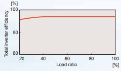
Total inverter efficiency as high as approximate 97%.
- Because an output transformer is unnecessary, inherent losses are eliminated.
- Multi-level PWM control minimizes switching loss.
- Because the harmonic current on the power source side is reduced, the primary winding of the input transformer has a reduced harmonic losses.
Total inverter efficiency curve (including input transformer).
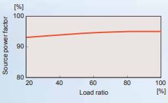
Source power factor as high as 95% or more.
- Due to full-wave rectification with multi-phase diodes, operation is allowed with the source power factor (power factor on power source side) set at a high level.
- A phase advancing capacitor and a DC reactor for improving the source power factor are unnecessary.
- A smaller power capacity suffices for inverter operation.
Source power factor curve.
High-reliability.
- Higher equipment reliability is achieved by reducing the number of inverter cells by using a single-phase, 3-level inverter, etc.
- Stable operation is maintained despite load fluctuations, by the simple sensor-less vector control function.
- The control device has a 32-bit MPU for quick response and high-accuracy
Vector control.
Vector control with a speed sensor is available (as an option) for equipment having high speed and torque accuracy requirements. (option).
Easy maintenance.
- The inverter is air-cooled, requiring no cooling water.
- Start/stop operation, parameter setting, fault display and data monitoring are performed on the touch panel with simple loader functions.
- Simple, built-in auto-tuning functions facilitate testing and adjustment.
- Fault diagnoses are easily performed.
- A dry-type input transformer is adopted.
Fuji Electric Medium-Voltage drives Industry Applications
Construction Materials.
- Kiln head cooling fans
- Kiln tail heating fans
- Grinders
- Cement rotary kilns
Petrochemical.
- Catalytic cracking unit
- Hydrogenation compressor
- Oil and gas transmission device
- Blowers/pumps/pelletizer
Mining.
- Belt conveyers
- Grinders
- Mine air circulation blowers
Iron and steel.
- Blast fumace blowers
- Primary/secondary dust blowers
- Dry quenched coke circulation blower
- High-pressure phosphorus ejector pump
- Blowers/water pumps
- Crusher
Electric power.
- Induced draft fan/forced draught fan
- Primary/secondary blowers
- Condensation pumps
- Recirculation pumps
- Feed pumps
Others.
- Water conservancy, utilities (pumps)
- Sugaring (mill)
- Test crew
- Internal mixer
Reasonable circuit structure.
High-reliability and simple-maintenance inverters utilizing the latest power electronics such as 3-level inverter, mounting of special MPU and no need for harmonic filter/power-factor regulating capacitor.
Master control PC board.
- Mounting of a 32-bit MPU, and a special MPU in the voltage and current detection system offers a quick response and high accuracy.
- Incorporation of a simple sensor-less vector control function enables inverters to maintain stable operation irrespective of load fl uctuation even without a speed sensor.
Input multiplex-winding transformer.
- Harmonic current on the power source side is low due to a multiplex configuration of the secondary winding.
- Multi-pulse rectification (24 to 60 pulses) and the generation of harmonics meet the IEEE standard.
- Harmonic filters and power factor regulating capacitors are not needed.
- Because a dry-type input transformer is integrated in the panel, external cabling work between the input transformer and inverter panel is no longer necessary.
Cooling fan.
Air-cooled inverters make maintenance easy.
Inverter cell.
- The number of inverter cells has been substantially reduced by adopting a singlephase, 3-level inverter design.
- Each inverter cell alone can be replaced easily, because the controller, diodes, IGBT elements and DC intermediate capacitor are combined into an integral body.
Fuji Electric main circuit configuration.
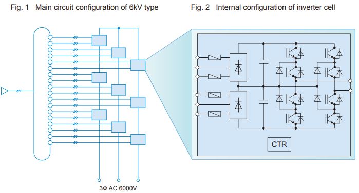
Main circuit configuration.
Principle of operation.
FRENIC4600FM5e consists of an input transformer and 9 inverter cells in case of the 6kV type as shown in Fig. 1 (the 10kV type has 12-15 inverter cells and the 4.16 and 3kV types have 6 inverter cells.). One inverter cell consists of a single-phase, 3-level inverter and can output 1,155V. As shown in Fig. 1, the 6kV type obtains a phase voltage of about 3,465V by connecting 3 inverter cells in series and a star connection of the vertical cell pairs can generate a line voltage of about 6,000V. Use of the single-phase, 3-level inverter doubles the output voltage obtainable from one cell when compared with a single-phase, 2-level inverter. Therefore, an output voltage can be obtained by using a smaller number of inverter cells. (See Figs. 3 and 4.)
Friendly to machines.
- The multi-level PWM control provides an almost sinusoidal output current waveform, thus reducing motor torque pulsation.
- Because the output current is almost sinusoidal, a motor suffers less loss due to harmonics.
- The multi-level (max. 21 levels) PWM control minimizes switching surge and thereby reduces stress on the motor.
- There is no need to reduce motor capacity after applying inverter drive.
- There is no need for special cables, etc. after applying inverter drive.
- This inverter is applicable not only to a square-law reduced torque load, but also to a constant torque load such as an extruder.
- For driving a large-capacity motor in a system that has a small power capacity, voltage fluctuation, etc. due to the starting current of a motor will cause problems. However, because the starting current can be suppressed by the soft start of this inverter, operation can be performed.
Fuji Electric function description.
Momentary interruption introduction.
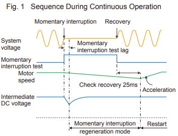
In the event of a voltage drop due to a momentary power interruption, the operation processing pattern can be selected according to the application.
- Selection of major fault at voltage drop due to momentary power interruption.
The inverter is stopped in the major fault status and the motor is set in the free run status.
- Selection of restart under free run (option)
Inverter operation is stopped and the motor is set in the free run status. Upon power recovery, the motor under deceleration in free run or under stop is automatically accelerated again through a speed search function.
- Selection of continuing operation at voltage drop due to momentary power interruption (option)
Inverter operation is continued without setting the motor in the free run status even when a voltage drop due to a momentary power interruption occurs. As soon as line voltage is recovered, the motor is accelerated again back to the operating speed.
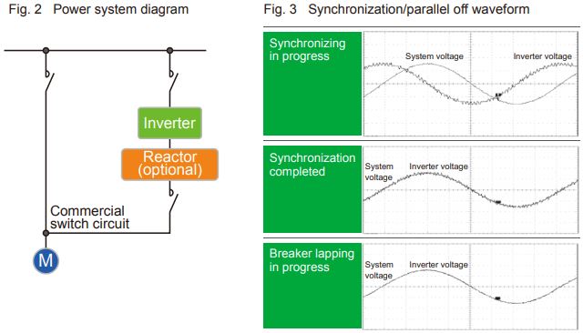
Synchronization undisturbed switch.
Shockless switching between inverter operation and commercial power operation allowed by phase control according to system voltage. (See Fig. 3.) (Synchronizing/parallel off function: option).
An electric reactor must be installed on the output side of the inverter to enable this function.
Control Functions.
The CPU for the FRENIC4600FM5e series of medium voltage inverter's basic control system (control, operation
program, and all types of interfaces), high speed computing electric current control system, and medium voltage
command processing and output voltage pulse waveform processing system has a 32-bit RISC processor.
The system provides the best control for all types of functions and internally integrates the following functions:
- Logic function.
Provides system operation and stoppage through software based on external logic and control signals.
- Regulation Function.
Provides the best regulation control based on the sampling control principle.
- Control Parameter Setting Function.
Can set all system control parameters through the operations panel, programmer, POD, or central
monitoring system and provide the best adjustment capability.


_series.png)
_series.png)
_series.png)
_series.png)
_series.png)
_series.png)
_soft_starters.png)


.png)


