Fuji Electric, Pressure transmitters FCX-AII V5 series
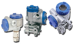
Excellent repeatability - Easy maintenance - High accuracy
- Available in a “Smart” version (4-20 mA + superimposed digital signal) with the Fuji proprietary protocol and the Hart® protocol
- Equipped with the Fieldbus Foundation H1 protocol (option)
- Manufactured according to ISO9001 standards
Integrated Safety Systems (IEC 61508)
- With a SIL 3 capability, the FCX-AII in its VG version is SIL2 (HFT=0) or SIL 3 (HFT=1) certified
- Its 97% safety failure ratio allows it to offer the best SFF available on the pressure transmitter market
- The FCX-AII VG has a sampling time of 40 ms and a response time of 80 ms, making it one of the fastest pressure transmitters on the market
Specifications
- Accuracy: ± 0.065% of the calibrated span (standard); ± 0.04% of the calibrated span (option)- Long term stability: ± 0.1% max.span /10 years
- Differential pressure transmitters for static pressure : up to 1035 bar (15 000 PSI)
- Various materials available for wetted parts : Tantalum, Monel, Hastelloy C, ou PVDF
- Applications : chemicals, petrochemicals, energy, steel-making, paper, food & beverage or water treatment
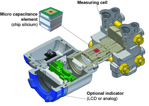
Fuji Electric FCX-AII V5 micro capacitance based technology
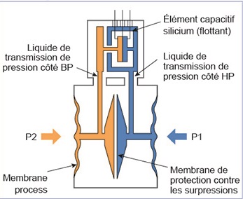
Micro capacitance silicon sensor
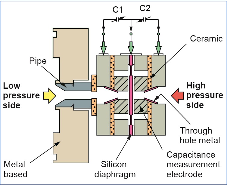
Based on our extensive silicon chip manufacturing experience,Fuji Electric developed the unique micro capacitancesilicon sensor as the centrepiece of FCX-AII transmitters. To minimise static pressure, overpressure temperature effects, It is assembled floating in the measuring cell neck.As a measuring diaphragm material, the sensor uses as a single crystal silicon that has minimal hysteresis and fatigue which improves the transmitter’s characteristics improving long term stability of zero and reliability.Thanks to 0,065% standard accuracy (up to 0,04% at option), a great rangeability of 100 :1 and the various materials available for wetted parts (Tantalum, Monel, Hastelloy-C or PVDF) our transmitters can be used in various applications in industry fields such as petrochemistry, chemistry, energy, iron industry, food industry and water treatment.
Measuring cell
The differential pressure is applied on the silicone sensor and changes the two capacitance values of the sensor. It is assembled floating in the measuring cell neck and improves the static pressure and temperature characteristics...
Fuji Electric FCX-AII V5 Optional functionality
Digital indicator
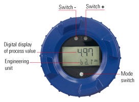
The FCX-All V5 transmitter may be equipped with an analog or digital indicator. The digital indicator is based on LCD technology and shows the information on 2 lines each of 6 digits and also includes 3 push buttons. The indicator enables the measurement in physical units and the local configuration of the transmitter.
- Zero/Span calibration without reference pressure service
- Linear or square root signal
- Damping
- Digital indicator configuration
- Zero/Span calibration
- Self-diagnosis
- Output circuit calibration
- Direction and value of burnout
Burnout current
In conformance with the recommendations of NAMUR NE 43, the output of the transmitter can be driven to a specific value should the transmitter experience an internal failure. The standard output signal limits are 3.2 to 22.5 mA. In case of a transmitter failure, the burnout direction can be down scaled (3.2 to 4 mA) or up scaled (20 to 22.5 mA), being programmable.

Maintenance functions
The calibration parameters are saved in the transmitter. At any time it is possible to come back to the factory calibration of the transmitter. Min and max temperatures are stored in the transmitter memory. It is always possible to visualize the values in a specific menu on the screen of the hand held communicator. All the adjustment functions of the transmitter can be locked by a password (the external adjusting screw is also locked).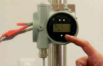
Fuji Electric FCX-AII V5 Communication
Hand held communicators
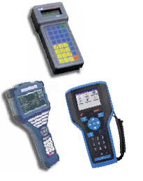
Fuji Electric hand held communicator is a very useful configuration tool for the FCX-AII V5 transmitter. As a menu driven device, the HHC can be used to remotely display and configure transmitter parameters (zero, span, burnout, output signal, auto diagnostic, type of output signal, damping, current generation, tag, model number of the transmitter etc.) Using the Hart® communication protocol, the FCX-AII V5 transmitter can also be configured by any Hart® protocol compatible hand held communicator.
Communication software Hart® Explorer
The FCX-AII V5 pressure transmitter can also be configured using Hart® communication based software “Hart® Explorer” connected to your Laptop or PC. Configuration of the above parameters is possible and the settings can also be saved for future reference. It’s also possible to measure and record process values. The interface between the PC and the transmitter is performed by a mini modem USB / Hart® to guarantee the communication between the PC and the 4 to 20 mA loop of the transmitter.
Transmitter measurement diaphragm materials
Hydrogen is the smallest atom element. So, it can penetrate the metal process diaphragms of pressure transmitters, reducing measurement accuracy and a transmitter's lifetime.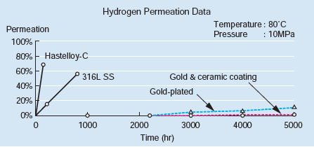
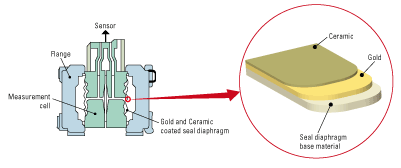
Since Fuji Electric's special seal diaphragm double coated with gold and ceramic significantly suppresses the hydrogen permeation, the transmitter is suitable for desulfurization facilities and hydrogen production units for petroleum refining.
Specifications
| Type | FKC | FKG | FKA | FKE | FKB | FKD | FKP | FKH |
|---|---|---|---|---|---|---|---|---|
| Appearance |
 Differential pressure (flow) |
 Pressure |
 Pressure |
 Level |
 Remote seal type Pressure |
 Remote seal type differential pressure (flow) |
 Pressure |
 Absolute Pressure |
| Maximum span (kPa) [URL] |
16 32 130 500 3000 20000 |
130 500 3000 10000 50000 |
16 130 500 3000 |
32 130 500 |
130 500 3000 10000 50000 |
32 130 500 |
130 500 3000 10000 |
130 500 3000 |
| Weight kg (No indicator) | 3,1 | 2,9 | 2,9 | 9-19 | 4-18 | 9-19 | 2 | 3 |
| Accuracy rating | ±0.04% (option)/±0.065% (standard) *Refer to the data sheets for details. | ±0.1% | ±0.2% | |||||
| Diaphragm materials |
316L SS Hastelloy-C Monel Tantalum 316L SS Gold-plated Gold & ceramic coating |
316L SS Hastelloy-C Monel Tantalum |
316L SS Hastelloy-C Monel Titanium Zirconium 316L SS Gold-plated |
316L SS | ||||
| Process connection | Rc1/4 | Flange | NPT1/2, Rc1/4, Rc1/2, NPT1/4 | |||||
| Common specifications |
Elevation / Suppression: -100 to +100%URL Span setting range: 1 to 1/100URLSetting interval: 60ms Temperature range: Sensor unit: -40 to +120°C (version for higher temperature available) Electronics: -40 to 85°C Power supply voltage: 10.5–45V DC Output signal / Allowable load resistance: 4–20mA DC/600Ω or less (When 24V DC is applied) |
Communication protocol: Fuji protocol or HART protocol Damping time constant: configurable between 0–32 s Zero/span adjustment: by adjustment screws, by optional field configurator, or by HHC. Electric cable inlet: G1/2, 1/2-14 NPT, pg13.5 or M20×1.5 Options: Analog indicator, digital indicator, cleaning for oxygen service, cleaning for chlorine service,stainless housing, stainless tag plate, field configurator |
||||||
FKC type pressure transmitters features and specifications
The FCX–AIII differential pressure (flow) transmitter accurately measures differential pressure, liquid level, gauge pressure or flow rate and transmits a proportional 4 to 20mA signal. The transmitter utilizes a unique micromachined capacitance silicon sensor with state-of-the-art microprocessor technology to provide exceptional performance and functionality.Features
High accuracy up to ±0.04%
0.065% accuracy as standard, 0.04% accuracy as option. Fuji’s micro-capacitance silicon sensor assures this accuracy for all elevated or suppressed calibration ranges without additional adjustment.
Minimum environmental influence
The “Advanced Floating Cell” design which protects the pressure sensor against changes in temperature, static pressure, and overpressure substantially reduces total measurement error in actual field applications.
Fuji/HART® bilingual communications protocol
FCX–AIII series transmitter offers bilingual communications to speak both Fuji proprietary protocol and HART®. Any HART® compatible devices can communicate with FCX–AIII.
Application flexibility
Various options that render the FCX–AIII suitable for almost any process applications include:
– Full range of hazardous area approvals
– Built-in RFI filter and lightning arrester
– 5-digit LCD meter with engineering unit
– Stainless steel electronics housing
– Wide selection of materials
Programmable output Linearization Function
In addition to Linear and Square Root, output signal can be freely programmable. (Up to 14 compensated points at approximation.)
Burnout current flexibility (Under Scale: 3.2 to 4.0mA, Over Scale: 20.0 to 22.5mA)
Burnout signal level is adjustable using Model FXW Hand Held Communicator (HHC) to comply with NAMUR NE43.
Dry calibration without reference pressure
Thanks to the best combination of unique construction of mechanical parts (Sensor unit) and high performance electronics circuit (Electronics unit), reliability of dry calibration without reference pressure is at equal level as wet calibration.
Functional specifications
Service:
Liquid, gas, or vapor
Static pressure, span, and range limit:
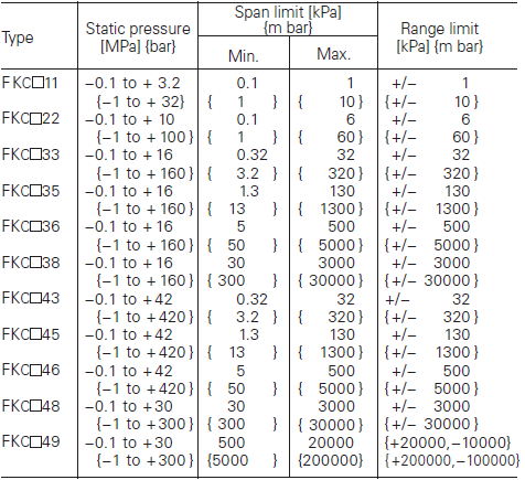
Remark : To minimize environmental influence, span should be greater than 1/40 of the max. span in most applications.
Important : For FKC #49. max possible overload pressure on LP side must be ≤ 100 bar. The accuracy in not guaranteed when used at negative DP.
Lower limit of static pressure (vacuum limit):
- Silicone fill sensor
- Fluorinated fill sensor: 66kPa abs (500mmHg abs) at temperature below 60°C
The maximum span of each sensor can be converted to different units using factors:
1MPa =103KPa=10bar=10.19716kgf/cm2 =145.0377psi
1kpa=10mbar=101.9716mmH2O=4.01463inH2O
Over range limit:
To maximum static pressure limit
Output signal:
4 to 20mA DC (linear or square root) with digital signal superimposed on the 4 to 20mA signal
Power supply:
Transmitter operates on 10.5V to 45V DC at transmitter terminals. 10.5V to 32V DC for the units with optional arrester.
Load limitations:
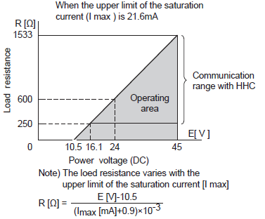
Note: For communication with HHC (Model: FXW), min. of 250 Ω required
Temperature limit:
- Ambient: −40 to +85°C
(−20 to +80°C for LCD indicator)
(−40 to +60°C for arrester option)
(−10 to +60°C for fluorinated oil filled transmitters)
For explosionproof units (flameproofor intrinsic safety), ambient temperature must be within the limits specified in each standard.
- Process: −40 to +120°C for silicone fill sensor; −20 to +80°C for fluorinated oil fill sensor
- Storage: −40 to +90°C
Humidity limit:
0 to 100% RH
Communication:
With HHC (Model FXW, consult Data Sheet No. EDS8-47), following items can be remotely displayed or configured. Note: HHC’s version must be higher than 7.0 (or FXW 1− 4), for FCX–AIII.
Local configurator with LCD display (option):
Local configurator with 3 push button and LCD display can support following items:
.png)
Zero/span adjustment:
Zero and span are adjustable from the HHC. Zero and span are also adjustable externally from the adjustment screw.
Damping:
Adjustable from HHC or local configurator unit with LCD display. The time constant is adjustable between 0.06 to 32 seconds.
Zero elevation/suppression:
−100% to +100% of URL
Normal/reverse action:
Selectable from HHC(1)
Indication:
Analog indicator or 5-digit LCD meter, as specified.
Burnout direction:
Selectable from HHC. If self-diagnostic detect transmitter failure, the analog signal will be driven to either “Output Hold”, “Output Overscale” or “Output Underscale” modes.
- “Output Hold”: Output signal is hold as the value just before failure happens.
- “Output Overscale”: Adjustable within the range 20.0mA to 21.6mA from HHC (Note: When the ambient temperature is -30°C or lower: 20.0mA to 20.8mA.)
- “Output Underscale”: Adjustable within the range 3.2mA to 4.0mA from HHC

Output limits conforming to NAMUR NE43 by order
Loop-check output:
Transmitter can be configured to provide constant signal 3.2mA through 21.6mA by HHC
Programmable output linearization function:
Output signal can be characterized with “14 points linear approximation function” from HHC
Performance specifications for linear output
Reference conditions, silicone oil fill, 316L SS isolating diaphragms, 4 to 20mA analog output in linear mode.
Accuracy rating (including linearity, hysteresis, and repeatability):
Max span 32kPa to 3000kPa model:
- For spans greater than 1/10 of URL: ±0.065% of span or ±0.04% of span (15th digit: H, T)
- For spans below 1/10 of URL:
Max span 20MPa model:
- For spans greater than 5Mpa: ±0.1% of span
- For spans below 5MPa:
Max span 1kPa, 6kPa model:
- For spans greater than 1/10 of URL: ±0.1% of span
- For spans below 1/10 of URL:
Stability:
±0.1% of upper range limit (URL) for 10 years for 6th digit code 3, 5, 6, 8 and 9.
Temperature effect:
Effects per 28°C change between the limits of −40°C and +85°C
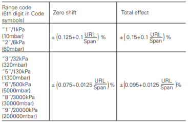
Static pressure effect:

Overrange effect:

Performance specifications for square root output
Accuracy rating:

Max span 1kPa, 6kPa model:

Temperature effect:
Effects per 28°C change between the limits of −40°C and +85°C.

Low flow cut-off:
Customer configurable for any point between 0 to 20% of output.
Performance specifications common for both atpt modes
Supply voltage effect:
Less than 0.005% of calibrated span per 1V.
Update rate:
60 msec
Step response:
(without electrical damping)

Mounting position effect:
- Zero shift, less than 0.12kPa {1.2m bar} for a 10° tilt in any plane.
- No effect on span.
- This error can be corrected by adjusting Zero.
Dielectric strength:
500V AC, 50/60Hz 1 min., between circuit and earth.
Insulation resistance:
More than 100MΩ at 500V DC.
Internal resistance for external field indicator:
12Ω or less
Physical specifications
Electrical connections:
G1/2, 1/2-14 NPT, Pg13.5, or M20 × 1.5 conduit, as specified.
Process connections:
1/4-18 NPT or Rc1/4 on 54mm centers, as specified. Meets DIN 19213.
Process-wetted parts material:
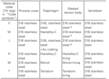
Remark: Availability of above material design depends on ranges and static pressure.
* 329J3L stainless steel on FKC 11 and FKC 22.
Non-wetted parts material:
- Electronics housing: Low copper die-cast aluminum alloy finished with polyester coating (standard), or 316 stainless steel, as specified.
- Bolts and nuts: Cr-Mo alloy (standard), 316 stainless steel (for static pressure code “1”, “2”, and “3” only), or 660 stainless steel (for static pressure code “3” and “4” only). Static pressure rating for code “3” with 316 stainless steel bolts is degraded to 10MPa.
- Fill fluid: Silicone oil (standard) or fluorinated oil
- Mounting bracket: 304 or 316 stainless steel
Environmental protection:
IEC IP67 and NEMA 6/6P
Mounting:
On 60.5mm(JIS 50A) pipe using mounting bracket, direct wall mounting, or direct process mounting.
Mass{weight}:
Transmitter approximately 3.1 to 3.6kg without options. Add; 0.5kg for mounting bracket 4.5kg for stainless steel housing option.
Optional features
Indicator:
A plug-in analog indicator (2.5% accuracy). An optional 5-digit LCD meter with engineering unit is also available.
Local configurator with LCD display:
An optional 5 digits LCD meter with 3 push buttons can support items as using communication with FXW.
Arrester:
A built-in arrester protects the electronics from lightning surges. Lightning surge immunity: 4kV (1.2 × 50µs).
Oxygen service:
Special cleaning procedures are followed throughout the process to maintain all process wetted parts oil-free. The fill fluid is fluorinated oil.
Chlorine service:
The fill fluid is fluorinated oil.
Degreasing:
Process-wetted parts are cleaned, but the fill fluid is standard silicone oil. Not for use on oxygen or chlorine measurement.
Vacuum service:
Special silicone oil and filling procedure are applied.
Optional tag plate:
An extra stainless steel tag with customer tag data is wired to the transmitter.
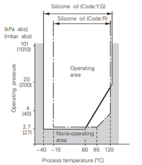
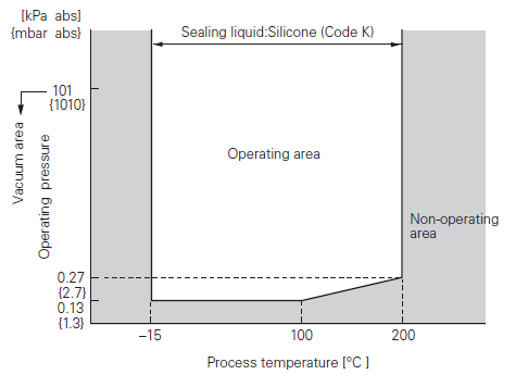
Relation between process temperature and operating pressure
FKG TYPE PRESSURE TRANSMITTERS FEATURES AND SPECIFICATIONS
The FCX–AIII pressure transmitter accurately measures gauge pressure and transmits a proportional 4 to 20mA signal. The transmitter utilizes a unique micromachined capacitance silicon sensor with state-of-the-art microprocessor technology to provide exceptional performance and functionality.Features
High accuracy up to ±0.04%
0.065% accuracy as standard, 0.04% accuracy as option. Fuji’s micro-capacitance silicon sensor assures this accuracy for all elevated or suppressed calibration ranges without additional adjustment.
Minimum environmental influence
The “Advance Floating Cell” design which protects the pressure sensor against changes in temperature, and overpressure substantially reduces total measurement error in actual field applications.
Fuji/HART® bilingual communications protocol
FCX–AIII series transmitter offers bilingual communications to speak both Fuji proprietary protocol and HART®. Any HART® compatible devices can communicate with FCX–AIII.
Application flexibility
Various options that render the FCX–AIII suitable for almost any process applications include:
- Full range of hazardous area approvals
- Built-in RFI filter and lightning arrester
- 5-digit LCD meter with engineering unit
- Stainless steel electronics housing
Burnout current flexibility (Under Scale: 3.2 to 4.0mA, Over Scale: 20.0 to 22.5mA)
Burnout signal level is adjustable using Model FXW Hand Held Communicator (HHC) to comply with NAMUR NE43.
Dry calibration without reference pressure
Thanks to the best combination of unique construction of mechanical parts (Sensor unit) and high performance electronics circuit (Electronics unit), reliability of dry calibration without reference pressure is at equal level as wet calibration.
Functional specifications
Service:
Liquid, gas, or vapor
Output signal:
4 to 20mA DC with digital signal superimposed on the 4 to 20mA signal.
Power supply: Transmitter operates on 10.5V to 45V DC at transmitter terminals. 10.5V to 32V DC for the units with optional arrester.
Span, range and overrange limit:
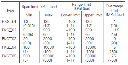
Remark: To minimize environmental influence, span should be greater than 1/40 of the max. span in most applications.
- Lower range limit (vacuum limit); silicone fill sensor; fluorinated fill sensor: 66kPa abs (500mmHg abs) at below 60°C
- Conversion factors to different units; 1 MPa=103 kPa=10bar=10.19716kgf/cm2= 145.0377psi
1kPa=10mbar=101.9716mmH2O =4.01463inH2O
Load limitations:
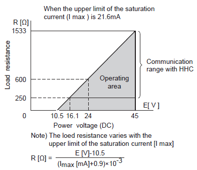
Note: For communication with HHC (Model: FXW), min. of 250Ω required.
Zero/span adjustment:
Zero and span are adjustable from the HHC. Zero and span are also adjustable externally from the adjustment screw.
Damping:
Adjustable from HHC or local configurator unit with LCD display. The time constant is adjustable between 0.06 to 32 seconds.
Zero elevation/suppression:
Zero can be elevated or suppressed within the specified range limit of each sensor model.
Normal/reverse action:
Selectable from HHC.
Indication:
Analog indicator or 5-digit LCD meter, as specified.
Burnout direction:
Selectable from HHC. If self-diagnostic detect transmitter failure, the analog signal will be driven to either “Output Hold”, “Output Overscale”or “Output Underscale” modes.
- “Output Hold”: Output signal is hold as the value just before failure happens.
- “Output Overscale”: Adjustable within the range 20.0mA to 21.6mA from HHC. (Note: When the ambient temperature is -30°C or lower: 20.0mA to 20.8mA.)
- “Output Underscale”: Adjustable within the range 3.2mA to 4.0mA from HHC.

Output limits conforming to NAMUR NE43 by order.
Loop-check output:
Transmitter can be configured to provide constant signal 3.2mA through 21.6mA by HHC.
Temperature limit:
- Ambient: −40 to +85°C
(−20 to +80°C for LCD indicator)
(−40 to +60°C for arrester option)
(−10 to +60°C for fluorinated oil fill transmitter)
For explosionproof units (flameproof or intrinsic safety), ambient temperature must be within the limits specified by each standard.
- Process: −40 to +100°C for silicone fill sensor; −20 to +80°C for fluorinated oil fill sensor
- Storage: −40 to +90°C
Humidity limit:
0 to 100% RH
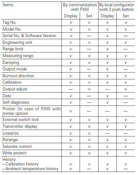
Communication:
With HHC (Model FXW, consult Data Sheet No. EDS8-47), following items can be remotely displayed or configured. Note: HHC’s version must be higher than 7.0 (or FXW____ 1– _4), for FCX - AIII.
Local configurator with LCD display (option):
Local configurator with 3 push button and LCD display can support following items.
Performance specifications
Reference conditions, silicone oil fill, 316L SS isolating diaphragms, 4 to 20mA analog output in linear mode.
Accuracy rating:
(including linearity, hysteresis, and repeatability)
Max span below 10000kPa model:
For spans greater than 1/10 of URL: ±0.065% of span or ±0.04% of span (15th digit: H, T)
For spans below 1/10 of URL:
Max span 50000kPa model:
For spans greater than 1/10 of URL: ±0.1% of span
For spans below 1/10 of URL:
Stability:
±0.1% of upper range limit (URL) for 10 years.
Temperature effect:
Effects per 28°C change between the limits of −40°C and +85°C. Zero shift: ±(0.075+0.0125 URL/span)%
Total effect: ±(0.095+0.0125 URL/span)%
Overrange effect:
Zero shift; 0.2% of URL for any overrange to maximum limit
Supply voltage effect:
Less than 0.005% of calibrated span per 1V.
Update rate:
60 msec
Step response:
Time constant: 0.08s (at 23°C). Dead time: approximately 0.12s (without electrical damping).
Mounting position effect:
Zero shift, less than 0.1kPa {1m bar} for a 10° tilt in any plane. No effect on span. This error can be corrected by adjusting Zero.
Dielectric strength:
500V AC, 50/60Hz 1 min., between circuit and earth.
Insulation resistance:
More than 100MW at 500V DC.
Internal resistance for external field indicator:
12Ω or less.
Physical specifications
Electrical connections:
G1/2, 1/2-14 NPT, Pg13.5, or M20 × 1.5 conduit, as specified.
Process connections:
1/4-18 NPT or Rc1/4 on 54mm centers, as specified. Meet DIN 19213
Process-wetted parts material:
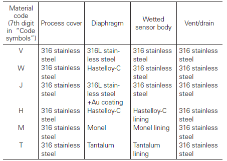
Remark: Availability of above material design depends on ranges. Refer to “Code symbols”.
Non-wetted parts material:
- Electronics housing: Low copper die-cast aluminum alloy finished with polyester coating (standard), or 316 stainless steel, as specified.
- Bolts and nuts: Cr-Mo alloy (standard), 316 stainless steel (660 stainless steel for 50MPa unit).
- Fill fluid: Silicone oil (standard) or fluorinated oil
- Mounting bracket: 304 or 316 stainless steel
Environmental protection:
IEC IP67 and NEMA 6/6P
Mounting:
On 60.5mm (JIS 50A) pipe using mounting bracket, direct wall mounting, or direct process mounting.
Mass {weight}:
Transmitter approximately 2.9 to 3.4kg without options. Add 0.5kg for mounting bracket and 4.5kg for stainless steel housing option
Optional features
Indicator:
A plug-in analog indicator (2.5% accuracy). An optional 5-digit LCD meter with engineering unit is also available.
Local configurator with LCD display:
An optional 5 digits LCD meter with 3 push buttons can support items as using communication with FXW.
Arrester:
A built-in arrester protects the electronics from lightning surges. Lightning surge immunity: 4kV (1.2 × 50μs)
Oxygen service:
Special cleaning procedures are followed throughout the process to maintain all process wetted parts oil-free. The fill fluid is fluorinated oil.
Chlorine service:
The fill fluid is fluorinated oil.
Degreasing:
Process-wetted parts are cleaned, but the fill fluid is standard silicone oil. Not for use on oxygen or chlorine measurement.
Vacuum service:
Special silicone oil and filling procedure are applied.
Optional tag plate:
An extra stainless steel tag with customer tag data is wired to the transmitter.
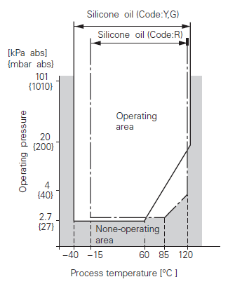
Relation between process temperature and operating pressure
FKA TYPE PRESSURE TRANSMITTERS FEATURES AND SPECIFICATIONS
The FCX -AIII absolute pressure transmitter accurately measures absolute pressure and transmits a proportional 4 to 20mA signal. The transmitter utilizes a unique micromachined capacitance silicon sensor with state-of-the-art microprocessor technology to provide exceptional performance and functionality.Features
High accuracy
0.2% accuracy for all calibrated spans is a standard feature for all AP models covering 1.6kPa {0.016bar} range to 3000kPa {30bar} high pressure range. 0.1% accuracy is available as option. Fuji’s micro-capacitance silicon sensor assures this accuracy for all suppressed calibration ranges without additional adjustment.
Minimum environmental influence
The “Advanced Floating Cell” design which protects the pressure sensor against changes in temperature, and overpressure substantially reduces total measurement error in actual field applications.
Fuji/HART® bilingual communications protocol
FCX -AIII series transmitter offers bilingual communications to speak both Fuji proprietary protocol and HART®. Any HART® compatible devices can communicate with FCX -AIII.
Application flexibility
Various options that render the FCX -AIII suitable for almost any process applications include:
- Full range of hazardous area approvals
- Built-in RFI filter and lightning arrester
- 5-digit LCD meter with engineering unit
- Stainless steel electronics housing
- Wide selection of materials
Burnout current flexibility (Under Scale: 3.2 to 4.0mA, Over Scale: 20.0 to 22.5mA)
Burnout signal level is adjustable using Model FXW Hand Held Communicator (HHC) to comply with NAMUR NE43.
Dry calibration without reference pressure
Thanks to the best combination of unique construction of mechanical parts (Sensor unit) and high performance electronics circuit (Electronics unit), reliability of dry calibration without reference pressure is at equal level as wet calibration.
Functional specifications
Service:
Liquid, gas, or vapor
Span, range and overrange limit:
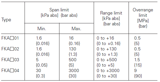
Remark: To minimize environmental influence, span should be greater than 1/40 of the max. span in most applications.
The maximum span of each sensor can be converted to different units using factors:
- 1MPa abs=103kPa abs=10bar abs=10.19716kgf/cm2 abs =145.0377psi abs
- 1kPa abs =10mbar abs=101.9716mmH2O abs =4.01463inH2O abs=7.50062mmHg abs
Output signal:
4 to 20mA DC with digital signal superimposed on the 4 to 20mA signal.
Power supply:
Transmitter operates on 10.5V to 45V DC at transmitter terminals. 10.5V to 32V DC for the units with optional arrester.
Load limitations:
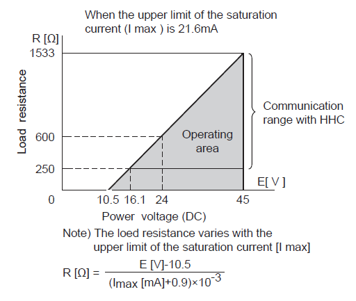
Note: For communication with HHC (Model: FXW), min. of 250Ω is required.
Zero/span adjustment:
Zero and span are adjustable from the HHC. Zero and span are also adjustable externally from the adjustment screw.
Damping:
Adjustable from HHC or local configurator unit with LCD display. The time constant is adjustable between 0.06 to 32 seconds.
Zero elevation/suppression:
Zero can be elevated within the specified range limit of each sensor model.
Normal/reverse action:
Selectable from HHC.
Indication:
Analog indicator or 5-digit LCD meter, as specified.
Burnout direction:
Selectable from HHC. If self-diagnostic detect transmitter failure, the analog signal will be driven to either “Output Hold”, “Output Overscale” or “Output Underscale” modes.
- “Output Hold”: Output signal is hold as the value just before failure happens.
- “Output Overscale”: Adjustable within the range 20.0mA to 21.6mA from HHC. (Note: When the ambient temperature is -30°C or lower: 20.0mA to 20.8mA.)
- “Output Underscale”: Adjustable within the range 3.2mA to 4.0mA from HHC.

Output Limits comforming the NAMUR NE43 by order.
Loop-check output:
Transmitter can be configured to provide constant signal 3.2mA through 21.6mA by HHC.
Temperature limit:
- Ambient: −40 to +85°C
(−20 to +80°C for LCD indicator)
(−40 to +60°C for arrester option)
For explosionproof units (flameproof or intrinsic safety), ambient temperature must be within the limits specified by each standard.
- Process: −40 to +85°C for silicone fill sensor
- Storage: −40 to +90°C
Humidity limit:
0 to 100% RH
Communication:
With HHC (Model FXW, consult Data Sheet No. EDS8-47), following items can be remotely displayed or configured. Note: HHC’s version must be higher than 7.0 (or FXW ___1– _4), for FCX - AIII.
Local configurator with LCD display (option):
Local configurator with 3 push button and LCD display can support following items:
.png)
Performance specifications
Reference conditions, silicone oil fill, 316L SS isolating diaphragms, 4 to 20mA analog output in linear mode.
Accuracy rating, (including linearity, hysteresis, and repeatability):
- Standard: For spans greater than 1/10 of URL: ±0.2% of span For spans below 1/10 of URL:

- Option (code:21th digit H): (Not available for Max span 16kPa abs, 130kPa abs) For spans greater than 1/10 of URL: ±0.1% of span For spans below 1/10 of URL:

Stability:
±0.2% of upper range limit (URL) for 10 years.
Temperature effect:
Effect per 28°C change between the limits of - 40°C and +85°C

Overrange effect: Zero shift; ±0.2% of URL for any overrange to maximum limit
Supply voltage effect:
Less than 0.005% of calibrated span per 1V
Update rate:
60 msec
Step response:
Time constant: 0.08 s (at 23°C). Dead time: 0.12 s (without electrical damping).
Mounting position effect:
Zero shift, less than 0.1kPa{1mbar} for a 10° tilt in any plane. No effect on span. This error can be cor- rected by adjusting zero.
Dielectric strength:
500V AC, 50/60Hz 1 min., between circuit and earth.
Insulation resistance:
More than 100MΩ at 500V DC.
Internal resistance for external field indicator:
12Ω or less
Physical specifications
Electrical connections:
G1/2, 1/2-14NPT, Pg13.5, or M20 x 1.5 conduit, as specified.
Process connections:
1/4-18 NPT or Rc1/4 on 54mm centers, as specified.
Process-wetted parts material:
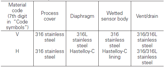
Remarks: Availability of above material design depends on ranges. Refer to “Code symbols”.
Non-wetted parts material:
Electronics housing: Low copper die-cast aluminum alloy finished with polyester coating (standard), or 316 stainless steel, as specified. Bolts and nut: Cr-Mo alloy (standard), 316 stainless steel. Fill fluid: Silicone oil Mounting bracket: 304 or 316 stainless steel.
Environmental protection:
IEC IP67 and NEMA 6/6P
Mounting:
On 60.5mm (JIS 50A) pipe using mounting bracket, direct wall mounting, or direct process mounting.
Mass{weight}:
Transmitter approximately 2.9 to 3.4kg without options. Add; 0.5kg for mounting bracket and 4.5kg for stainless steel housing option.
Optional features
Indicator:
A plug- in analog indicator (2.5% accuracy). An optional 5-digit LCD meter with engineering unit is also available.
Local configurator with LCD display:
An optional 5 digits LCD meter with 3 push buttons can support items as using communication with FXW.
Arrester:
A built-in arrester protects the electronics from lightning surges. Lightning surge immunity: 4kV (1.2 × 50μs).
Degreasing:
Process-wetted parts are cleaned, but the fill fluid is standard silicone oil. Not for use on oxygen or chlorine measurement.
Optional tagplate:
An extra stainless steel tag for customer tag data is wired to the transmitter.
FKE TYPE PRESSURE TRANSMITTERS FEATURES AND SPECIFICATIONS
The FCX -AIII level transmitter accurately measures liquid level and transmits a proportional 4 to 20mA signal. The transmitter utilizes a unique micromachined capacitance silicon sensor with state-of-the-art microprocessor technology to provide exceptional performance and functionality.Features
High accuracy
0.2% accuracy for all calibrated spans is a standard feature for all models covering 0.32kPa {3.2mbar} range to 500kPa {5bar} high differential pressure range. 0.1% accuracy is available as option. Fuji’s micro-capacitance silicon sensor assures this accuracy for all elevated or suppressed calibration ranges without additional adjustment.
Minimum environmental influence
The “Advanced Floating Cell” design which protects the pressure sensor against changes in temperature, static pressure, and overpressure substantially reduces total measurement error in actual field applications.
Fuji/HART® bilingual communications protocol
FCX -AIII series transmitter offers bilingual communications to speak both Fuji proprietary protocol and HART®. Any HART® compatible devices can communicate with FCX -AIII.
Application flexibility
Various options that render the FCX -AIII suitable for almost any process applications include:
- Full range of hazardous area approvals
- Built-in RFI filter and lightning arrester
- 5-digit LCD meter with engineering unit
- Stainless steel electronics housing
- Wide selection of materials
- High temperature, high vacuum service
Programmable output Linearization Function
Output signal can be freely programmable. (Up to 14 compensated points at approximation.)
Burnout current flexibility (Under Scale: 3.2 to 4.0mA, Over Scale: 20.0 to 22.5mA)
Burnout signal level is adjustable using Model FXW Hand Held Communicator (HHC) to comply with NAMUR NE43.
Dry calibration without reference pressure
Thanks to the best combination of unique construction of mechanical parts (Sensor unit) and high performance electronics circuit (Electronics unit), reliability of dry calibration without reference pressure is at equal level as wet calibration.
Functional specifications
Service:
Liquid, gas, or vapor
Static pressure, span, and range limit:
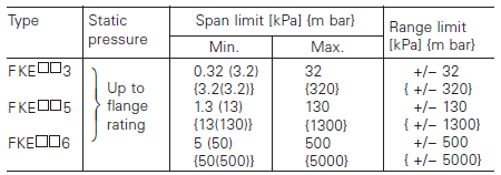
Remark: To minimize environmental influence, span should be greater than 1/40 of the max. span in most applications.
Note: Minimum span for flange whose diameter is 50A/2B/2 inch or smaller are shown in parentheses.
- Lower limit of static pressure (vacuum limit); Silicone fill sensor: see image below. Fluorinated fill sensor: 66kPa abs (500mmHg abs) at temperature below 60 °C.
- The maximum span of each sensor can be converted to different units using factors: 1MPa=103kPa=10bar=10.19716kgf/cm2=145.0377psi
1kPa=10mbar=101.9716mmH2O=4.01463inH2O
Overrange limit:
To maximum static pressure limit
Output signal:
4 to 20mA DC with digital signal superimposed on the 4 to 20mA signal
Power supply:
Transmitter operates on 10.5V to 45V DC at transmitter terminals. 10.5V to 32V DC for the units with optional arrester.
Load limitations:
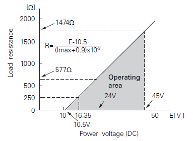
Note: For communication with HHC(1) (Model: FXW), min. of 250Ω required.
Zero/span adjustment:
Zero and span are adjustable from the HHC. Zero and span are also adjustable externally from the adjustment screw.
Damping:
Adjustable from HHC or local configurator unit with LCD display. The time constant is adjustable between 0.06 to 32 seconds.
Zero elevation/suppression:
−100% to + 100% of URL
Normal/reverse action:
Selectable from HHC
Indication:
Analog indicator or 5-digit LCD meter, as specified.
Burnout direction:
Selectable from HHC(1) If self-diagnostic detect transmitter failure, the analog signal will be driven to either “Output Hold”, “Output Overscale” or “Output Underscale” modes.
- “Output Hold”: Output signal is hold as the value just before failure happens.
- “Output Overscale”: Adjustable within the range 20.0mA to 21.6mA from HHC (Note: When the ambient temperature is -30°C or lower: 20.0mA to 20.8mA.)
- “Output Underscale”: Adjustable within the range 3.2mA to 4.0mA from HHC

Output Limits comforming the NAMUR NE43 by order.
Loop-check output:
Transmitter can be configured to provide constant signal 3.2mA through 21.6mA by HHC
Temperature limit:
- Ambient: −40 to + 85°C
(−20 to + 80°C for LCD indicator)
(−40 to + 60°C for arrester option)
(−10 to + 60°C for fluorinated oil fill transmitter)
For explosionproof units (flameproof or intrinsic safety), ambient temperature must be within the limits specified in each standard.
- Process:
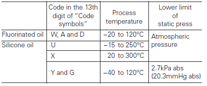
Low pressure side contact liquid temperature on transmitter of Code H, J is 120°C or lower.
- Storage: −40 to + 90°C
Humidity limit:
0 to 100% RH
Communication:
With HHC(1) (Model FXW, consult Data Sheet No. EDS8-47), following items can be remotely displayed or configured. Note: HHC’s version must be higher than 7.0 (or FXW ____1– _4), for FCX -AIII.
Local configurator with LCD display (option):
Local configurator with 3 push button and LCD display can support following items.
.png)
Programmable output linearization function:
Output signal can be characterized with “14 points linear approximation function” from HHC.
Performance specifications
Reference conditions, silicone oil fill, 316L SS isolating diaphragms, 4-20 mA analog output in linear mode.
Accuracy rating (including linearity, hysteresis, and repeatability):
- Standard: for spans greater than 1/10 of URL: ±0.2% of span
For spans below 1/10 of URL

- Option: (Code: 21th digit H, K)
For span greater than 1/10 of URL: 0.1% of span
For span below 1/10 of URL

Stability:
±0.2% of upper range limit (URL) for 10 years.
Temperature effect:
Effects per 28°C change between the limits of −40°C and +85°C.
- Standard:
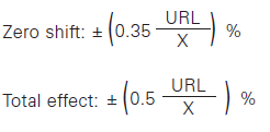
- Option: (Code: 21th digit J, K) Zero shift: ±0.3% (X>1/4URL)
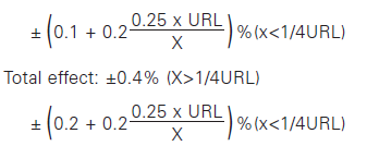
Static pressure effect:
Zero shift: ±0.2% of URL / 1MPa
Span shift: −0.2% of calibrated span / 1MPa
Overrange effect:
Zero shift; ±0.1% of URL for flange rating pressure
Supply voltage effect:
Less than 0.005% of calibrated span per 1V
Update rate:
60 msec
Step response:

Mounting position effect:
Zero shift, less than 0.3kPa {3m bar} for a 10° tilt in any plane. (No extension) No effect on span. This error can be corrected by adjusting zero.
Dielectric strength:
500V AC, 50/60Hz 1 min., between circuit and earth.
Dielectric strength:
500V AC, 50/60Hz 1 min., between circuit and earth.
Insulation resistance:
More than 100MΩ at 500V DC.
Internal resistance for external field indicator:
12Ω or less
Physical specifications
Electrical connections:
G1/2, 1/2-14 NPT, Pg13.5, or M20 x 1.5 conduit, as specified.
Process connections:
LP side: 1/4-18 NPT or Rc1/4. HP side: ANSI, DIN, or JIS raised face flange. See OUTLINE DIAGRAM for detailed dimensions. Refer to “Code symbols”.
Process-wetted parts material:
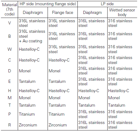
Process cover: 316 stainless steel
Remark: Sensor O-rings: Viton O-ring and teflon gasket selectable.
Non-wetted parts material:
- Electronics housing: Low copper die-cast aluminum alloy finished with polyester coating (standard), or 316 stainless steel, as specified.
- Bolts and nuts: Cr-Mo alloy (standard) or 304 stainless steel.
- Fill fluid: Silicone oil (standard) or fluorinated oil.
- Mounting flange: 316L stainless steel.
Environmental protection:
IEC IP67 and NEMA 6 / 6P
Mass {weight}:
Transmitter approximately 10.2 to 19.2kg without options. Add; 0.5kg for mounting bracket 4.5kg for stainless steel housing option and 1.0kg per 50mm extension of diaphragm.
FKB TYPE PRESSURE TRANSMITTERS FEATURES AND SPECIFICATIONS
The FCX -AIII pressure transmitter accurately measures gauge pressure and transmits a proportional 4 to 20mA signal. The transmitter utilizes a unique micromachined capacitance silicon sensor with state-of-the-art microprocessor technology to provide exceptional performance and functionality. Totally welded construction of the seals assures excellent reliability in high temperature and highly corrosive process conditions.Features
High accuracy
0.2% accuracy for all calibrated spans is a standard feature for all GP models covering 1.3kPa {0.013bar} range to 50000kPa {500bar} high pressure range. 0.1% accuracy is available as option. Fuji’s micro-capacitance silicon sensor assures this accuracy for all elevated or suppressed calibration ranges without additional adjustment.
Minimum environmental influence
The “Advanced Floating Cell” design which protects the pressure sensor against changes in temperature, and overpressure substantially reduces total measurement error in actual field applications.
Fuji/HART® bilingual communications protocol
FCX -AIII series transmitter offers bilingual communications to speak both Fuji proprietary protocol and HART®. Any HART® compatible devices can communicate with FCX -AIII.
Application flexibility
Various options that render the FCX -AIII suitable for almost any process applications include:
− Full range of hazardous area approvals
− Built-in RFI filter and lightning arrester
− 5-digit LCD meter with engineering unit
− Stainless steel electronics housing
− Wide selection of materials
− High temperature, high vacuum seals
Burnout current flexibility (Under Scale: 3.2 to 4.0mA, Over Scale: 20.0 to 22.5mA)
Burnout signal level is adjustable using Model FXW Hand Held Communicator (HHC) to comply with NAMUR NE43.
Dry calibration without reference pressure
Thanks to the best combination of unique construction of mechanical parts (Sensor unit) and high performance electronics circuit (Electronics unit), reliability of dry calibration without reference pressure is at equal level as wet calibration.
Functional specifications
Service:
Liquid, gas, or vapor
Span, range, and overrange limit:
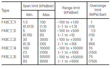
Remark: To minimize environmental influence, span should be greater than 1/40 of the max. span in most applications.
Note: Refer to code symbols for the detail of span limit.
− Lower range limit (vacuum limit); silicone fill sensor, fluorinated fill sensor: atmospheric pressure.
− Conversion factors to different units; 1MPa=103kPa=10bar=10.19716kgf/cm2=145.0377psi
1kPa=10mbar=101.9716mmH2O=4.01463inH2O
Output signal:
4 to 20mA DC with digital signal superimposed on the 4 to 20mA signal.
Power supply:
Transmitter operates on 10.5V to 45V DC at transmitter terminals.
Load limitations:
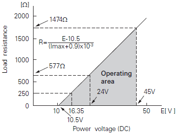
Note: for communication with HHC (Model: FXW), min. of 250Ω is required.
Zero/span adjustment:
Zero and span are adjustable from the HHC. Zero and span are also adjustable externally from the adjustment screw.
Damping:
Adjustable from HHC or local adjustment unit with LCD display. The time constant is configurator between 0.06 to 32 seconds.
Zero elevation/suppression:
Zero can be elevated or suppressed within the specified range limit of each sensor model.
Normal/reverse action:
Selectable from HHC.
Indication:
Analog indicator or 5-digit LCD meter, as specified.
Burnout direction:
Selectable from HHC. If self-diagnostic detect transmitter failure, the analog signal will be driven to either “Output Hold”, “Output Overscale” or “Output Underscale” modes.
- “Output Hold”: output signal is hold as the value just before failure happens.
- “Output Overscale”: adjustable within the range 20.0mA to 21.6mA from HHC. (Note: when the ambient temperature is -30°C or lower: 20.0mA to 20.8mA.)
- “Output Underscale”: Adjustable within the range 3.2mA to 4.0mA from HHC.

Output Limits comforming the NAMUR NE43 by order.
Loop-check output:
Transmitter can be configured to provide constant signal 3.2mA through 21.6mA by HHC.
Temperature limit:
- Ambient: −40 to +85°C
(−20 to +80°C for LCD indicator)
(−40 to +60°C for arrester option)
(−10 to +60°C for fluorinated oil fill transmitter)
(−10 to +85°C for silicone oil “U”, “S”, “K”) *
(+20 to +85°C for silicone oil “X”) *
* In case of capillary length is more than 7m, max. temperature is +55°C.
For explosionproof units (flameproof or intrinsic safety), ambient temperature must be within the limits specified by each standard
- Process:
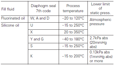
- Storage: −40 to +90°C
Humidity limit:
0 to 100% RH
Communication:
With HHC (Model FXW, consult Data Sheet No. EDS8-47), following items can be remotely displayed or configured. Note: HHC’s version must be higher than 7.0 (or FXW ____1– _4), for FCX - AIII.
Local configurator with LCD display (option):
Local configurator with 3 push button and LCD display can support following items:
.png)
Performance specifications
Reference conditions, silicone oil fill, 316L SS isolating diaphragms, 4 to 20mA analog output in linear mode.
Accuracy rating (including linearity, hysteresis, and repeatability):
- Standard:
For spans greater than 1/10 of URL: ±0.2% of span
For spans below 1/10 of URL:
- Option: (Code; 15th digit H, K, T, G)
Not available for Max span 50000kPa model.
For spans greater than 1/10 of URL: ±0.1% of span
For spans below 1/10 of URL:
Stability:
±0.2% of upper range limit (URL) for 10 years.
Temperature effect:
Effect per 28°C change between the limits of - 40°C and +85°C
- Standard:
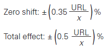
- Option (code; 15th digit J, K, F, G):
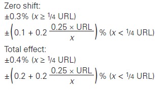
Overrange effect:
Zero shift; 0.2% of URL for any overrange to maximum limit
Supply voltage effect:
Less than 0.005% of calibrated span per 1V
Update rate:
60 msec
Step response:
Time constant: 0.3s (at 23°C); Dead time: 0.12s (without electrical damping).
Dielectric strength:
500V AC, 50/60Hz 1 min., between circuit and earth.
Insulation resistance:
More than 100MΩ/500V DC.
Internal resistance for external field indicator:
12Ω or less
Physical specifications
Electrical connections:
G1/2, 1/2-14 NPT, Pg13.5, or M20 × 1.5 conduit, as specified.
Process connections:
JIS, ANSI, or DIN raised face flanges or screw connection JIS/ISO G1 external thread. (Refer to “Code symbols.”)
Process-wetted parts material:
-Diaphragm: 316L stainless steel, Hastelloy-C Monel, Tantalum, Titanium or Zirconium
- Flange face: 316L stainless steel, Hastelloy-C Monel, Tantalum, Titanium or Zirconium
- Extension: 316 stainless steel
(Refer to “Code symbols”)
Non-wetted parts material:
- Electronics housing: Low copper die-cast aluminum alloy, or 316 stainless steel.
- Capillary: PVC or stainless steel, as specified in 6th digit of diaphragm seal code.
- Mounting flange: 316L stainless steel
- Fill fluid: Silicone oil (standard) or fluorinated oil
- Mounting bracket: 304 stainless steel
Environmental protection:
IEC IP67 and NEMA 6/6P
Mounting:
On 60.5mm (JIS 50A) pipe using mounting bracket, direct wall mounting.
Mass {weight}:
Transmitter approximately 8.2 to 11.2kg without options. Add; 0.5kg for mounting bracket and 4.5kg for stainless steel housing option. 1.5kg per 50mm extension of diaphragm.
Optional features
Indicator:
A plug-in analog indicator (2.5% accuracy). An optional 5-digit LCD meter with engineering unit is also available.
Local configurator with LCD display:
An optional 5 digits LCD meter with 3 push buttons can support items as using communication with FXW.
Arrester:
A built-in arrester protects the electronics from lightning surges. Lightning surge immunity: 4kV (1.2 × 50μs).
Oxygen service:
Special cleaning procedures are followed throughout the process to maintain all process wetted parts oil-free. The fill fluid is fluorinated oil.
Chlorine service:
Oil-free procedures as above. Includes fluorinated oil for fill.
Degreasing:
Process-wetted parts are cleaned, but the fill fluid is standard silicone oil. Not for use on oxygen or chlorine measurement.
Vacuum and high temperature service:
Special silicone oil and filling procedure are applied.
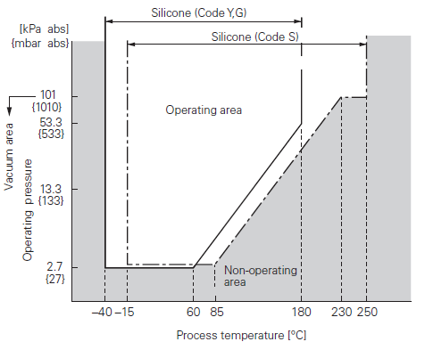
Optional tag plate:
An extra stainless steel tag for customer tag data is wired to the transmitter.
Accessories:
Hand-held communicator (Model FXW, refer to Data Sheet No. EDS8-47).
FKD TYPE PRESSURE TRANSMITTERS FEATURES AND SPECIFICATIONS
The FCX–AIII differential pressure transmitter accurately measures differential pressure, liquid level or gauge pressure and transmits a proportional 4 to 20mA signal. The transmitter utilizes a unique micromachined capacitance silicon sensor with state-of-the-art microprocessor technology to provide exceptional performance and functionality. Totally welded construction of the seals assures excellent reliability in high temperature and highly corrosive process conditions.Features
High accuracy
0.2% accuracy for all calibrated spans is a standard feature for all DP models covering 0.32kPa {3.2mbar} range to 500kPa {5bar} high differential pressure range. 0.1% accuracy is available as option. Fuji’s micro-capacitance silicon sensor assures this accuracy for all elevated or suppressed calibration ranges without additional adjustment.
Minimum environmental influence
The “Advanced Floating Cell” design which protects the pressure sensor against changes in temperature, static pressure, and overpressure substantially reduces total measurement error in actual fi eld applications.
Fuji/HART® bilingual communications protocol
FCX–AIII series transmitter offers bilingual communications to speak both Fuji proprietary protocol and HART®. Any HART® compatible devices can communicate with FCX–AIII.
Application fl exibility
Various options that render the FCX–AIII suitable for almost any process applications include:
– Full range of hazardous area approvals
– Built-in RFI filter and lightning arrester
– 5-digit LCD meter with engineering unit
– Stainless steel electronics housing
– Wide selection of materials
– High temperature, high vacuum seals
Programmable output Linearization Function
In addition to Linear and Square Root, output signal can be freely programmable. (Up to 14 compensated points at approximation.)
Burnout current fl exibility (Under Scale: 3.2 to 4.0mA, Over Scale: 20.0 to 22.5mA)
Burnout signal level is adjustable using Model FXW Hand Held Communicator (HHC) to comply with NAMUR NE43.
Dry calibration without reference pressure
Thanks to the best combination of unique construction of mechanical parts (Sensor unit) and high performance electronics circuit (Electronics unit), reliability of dry calibration without reference pressure is at equal level as wet calibration.
Functional specifications
Service:
Liquid, gas, or vapor
Static pressure, span, and range limit:
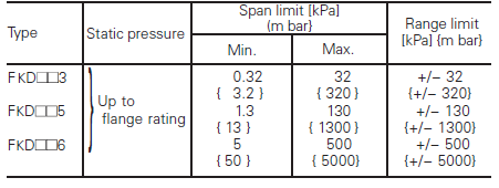
Remark : To minimize environmental influence, span should be greater than 1/40 of the max. span in most applications.
Note: Refer to code symbols for the detail of span limit.
– Lower limit of static pressure (vacuum limit); silicone fi ll sensor; fluorinated fi ll sensor: atmospheric pressure
– The maximum span of each sensor can be converted to different units using factors:
1MPa =103kPa=10bar=10.19716kgf/cm2 =145.0377psi
1kPa=10mbar=101.976mmH2O=4.01463H2O
Overrange limit:
To maximum static pressure limit
Output signal:
4 to 20mA DC (linear or square root) with digital signal superimposed on the 4 to 20mA signal.
Power supply:
Transmitter operates on 10.5V to 45V DC at transmitter terminals. 10.5V to 32V DC for the units with optional arrester.
Load limitations:
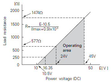
Note: For communication with HHC (Model: FXW), min. of 250W is required.
Zero/span adjustment:
Zero and span are adjustable from the HHC. Zero and span are also adjustable externally from the adjustment screw.
Damping:
Adjustable from HHC or local configurator unit with LCD display. The time constant is adjustable between 0.06 to 32 seconds.
Zero elevation/suppression:
−100% to +100% of URL
Normal/reverse action:
Selectable from HHC
Indication:
Analog indicator or 5-digit LCD meter, as specified.
Burnout direction:
Selectable from HHC. If self-diagnostic detect transmitter failure, the analog signal will be driven to either “Output Hold”, “Output Overscale” or “Output Underscale” modes.
- “Output Hold”: Output signal is hold as the value just before failure happens.
- “Output Overscale”: Adjustable within the range 20.0mA to 21.6mA from HHC. (Note: when the ambient temperature is -30°C or lower: 20.0mA to 20.8mA.)
- “Output Underscale”: Adjustable within the range 3.2mA to 4.0mA from HHC.

Output limits conforming to NAMUR NE43 by order.
Loop-check output:
Transmitter can be configured to provide constant signal 3.2mA through 21.6mA by HHC.
Temperature limit:
- Ambient: −40 to + 85°C
(−20 to + 80°C for LCD indicator)
(−40 to + 60°C for arrester option)
(−10 to + 60°C for fluorinated oil fill transmitter)
(−10 to + 85°C for silicone oil “U”, “S”, “K”) *
(+ 20 to + 85°C for silicone oil “X”) *
*In case of capillary length is more than 7m, max temperature is +55°C.
For explosionproof units (flameproof or intrinsic safety), ambient temperature must be within the limits specified in each standard.
- Process:
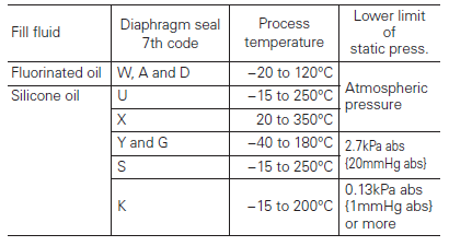
- Storage: −40 to +90°C
Humidity limit:
0 to 100% RH
Communication:
With HHC (Model FXW, consult Data Sheet No. EDS8-47), following items can be remotely displayed or configured. Note: HHC’s version must be higher than 7.0 (or FXW ____1− _4), for FCX–AIII.
Local configurator with LCD display (option):
Local configurator with 3 push button and LCD display can support following items:
.png)
Programmable output linearization function:
Output signal can be characterized with “14 points linear approximation function” from HHC.
Performance specifications
Reference conditions, silicone oil fill, 316L SS isolating diaphragms, 4 to 20mA analog output in linear mode.
Accuracy rating (including linearity, hysteresis, and repeatability):
- Standard: for spans greater than 1/10 of URL: 0.2% of span. For spans below 1/10 of URL:
- Option: (Code; 15th digit H, K, T, G)
For spans greater than 1/10 of URL: 0.1% of span
For spans below 1/10 of URL:
Stability:
±0.2% of upper range limit (URL) for 10 years.
Temperature effect (*):
Effects per 28°C change between the limits of −40°C and +85°C
- Standard:
Zero shift: ±0.35% of URL
Total effect: ±0.5% of URL
- Option (Code; 15th digit J, K, F, G):
Zero shift: ±0.3% of URL
Total effect: ±0.4% of URL
Note: * Excluding effect by temperature difference between the seals.
Static pressure effect:
Zero shift; 0.2% of URL / 1MPa
Span shift: −0.2% of calibrated span / 1MPa
Overrange effect:
Zero shift; 0.1% of URL for flange rating pressure.
Supply voltage effect:
Less than 0.005% of calibrated span per 1V
Update rate:
60 msec
Step response (without electrical damping):

Dielectric strength:
500V AC, 50/60Hz 1 min., between circuit and earth.
Insulation resistance:
More than 100MW at 500V DC.
Internal resistance for external field indicator:
12Ω or less
Physical specifications
Electrical connections:
G1/2, 1/2-14 NPT, Pg13.5, or M20 × 1.5 conduit, as specified.
Process connections:
JIS, ANSI, or DIN raised face flanges.
- JIS: 10K80A, 10K100A, 30K80A, or 30K100A
- ANSI: 150LB 3", 150LB 4", 300LB 3", or 300LB 4"
- DIN: PN40 DN80 or PN16 DN100
Diaphragm extension:
0, 50, 100, 150, or 200mm as specified. (Extended diaphragm is available only with 316L stainless steel diaphragm.)
Process-wetted parts material:
- Diaphragm: 316L stainless steel, Hastelloy-C, Monel, Tantalum, Titanium or Zirconium
- Flange face: 316L stainless steel, Hastelloy-C lining, Monel lining or Tantalum lining
- Extension: 316 stainless steel
Non-wetted parts material:
- Electronics housing: Low copper die-cast aluminum alloy or 316 stainless steel.
- Capillary: PVC or stainless steel, as specified in 6th digit of diaphragm seal code.
- Mounting flange: 316L stainless steel
- Fill fluid: Silicone oil (standard) or fluorinated oil
- Mounting bracket: 304 stainless steel
Environmental protection:
IEC IP67 and NEMA 6/6P
Mounting:
On 60.5mm (JIS 50A) pipe using mounting bracket, direct wall mounting.
Mass {weight}:
Transmitter approximately 12 to 31kg without options. Add; 0.5kg for mounting bracket, 4.5kg for stainless steel housing option and 1.5kg per 50mm extension of diaphragm.
Optional features
Indicator:
A plug-in analog indicator (2.5% accuracy). An optional 5-digit LCD meter with engineering unit is also available.
Local configurator with LCD display:
An optional 5 digits LCD meter with 3 push buttons can support items as using communication with FXW.
Arrester:
A built-in arrester protects the electronics from lightning surges. Lightning surge immunity: 4kV (1.2 × 50μs)
Oxygen service:
Special cleaning procedures are followed throughout the process to maintain all process wetted parts oil-free. The fill fluid is fluorinated oil.
Chlorine service:
Oil-free procedures as above. Includes fluorinated oil for fill.
Degreasing:
Process-wetted parts are cleaned, but the fill fluid is standard silicone oil. Not for use on oxygen or chlorine measurement.
Vacuum service:
Special silicone oil and filling procedure are applied.
Optional tag plate:
An extra stainless steel tag for customer tag data is wired to the transmitter.
Accessories:
Hand-held communicator: (Model FXW, refer to Data Sheet No. EDS 8-47)
FKP TYPE PRESSURE TRANSMITTERS FEATURES AND SPECIFICATIONS
The FCX–AIII pressure transmitter accurately measures gauge pressure and transmits proportional 4 to 20mA signal. The transmitter utilizes the unique micromachined capacitive silicon sensor with state-of-the-art microprocessor technology to provide exceptional performance and functionality.Features
High accuracy ±0.1%
0.1% accuracy is a standard feature. Fuji’s micro-capacitance silicon sensor assures this accuracy for all elevated or suppressed calibration ranges without additional adjustment.
Minimum environmental influence
The “Advance Floating Cell” design which protects the pressure sensor against changes in temperature, and overpressure substantially reduces total measurement error in actual field applications.
Fuji/HART® bilingual communications protocol
FCX–AIII series transmitter offers bilingual communications to speak both Fuji proprietary protocol and HART®. Any HART® compatible devices can communicate with FCX–AIII.
Application flexibility
Various options that render the FCX–AIII suitable for almost any process applications include:
– Full range of hazardous area approvals
– Built-in RFI filter and lightning arrester
– 5-digit LCD meter with engineering unit
Burnout current flexibility (Under Scale: 3.2 to 4.0mA, Over Scale: 20.0 to 22.5mA)
Burnout signal level is adjustable using Model FXW Hand Held Communicator (HHC) to comply with NAMUR NE43.
Dry calibration without reference pressure
Thanks to the best combination of unique construction of mechanical parts (Sensor unit) and high performance electronics circuit (Electronics unit), reliability of dry calibration without reference pressure is at equal level as wet calibration.
Functional specifications
Service:
Liquid, gas, or vapor
Span, range and overrange limit:
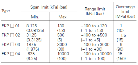
— Lower range limit (vacuum limit) is;
Silicone fill sensor
Fluorinated fill sensor: 66kPa abs (500mmHg abs) at below 60°C
Output signal:
4 to 20mA DC with digital signal superimposed on the 4 to 20mA signal.
Power supply:
Transmitter operates on 10.5V to 45V DC at transmitter terminals. 10.5V to 32V DC for the units with optional arrester.
Load limitations:
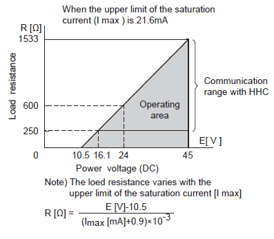
Note: For communication with HHC (Model: FXW), min. of 250 W required.
Zero/span adjustment:
Zero and span are adjustable from the HHC. Zero and span are also adjustable externally from the adjustment screw.
Damping:
Adjustable from HHC or local configurator unit with LCD display. The time constant is adjustable between 0.06 to 32 seconds.
Zero elevation/suppression:
Zero can be elevated or suppressed within the specified range limit of each sensor model.
Normal/reverse action:
Selectable from HHC.
Indication:
Analog indicator or 5-digit LCD meter, as specified.
Burnout direction:
Selectable from HHC. If self-diagnostic detect transmitter failure, the analog signal will be driven to either “Output Hold”, “Output Overscale” or “Output Underscale” modes.
- “Output Hold”: Output signal is hold as the value just before failure happens.
- “Output Overscale”: Adjustable within the range 20.0mA to 21.6mA from HHC. (Note: when the ambient temperature is -30°C or lower: 20.0mA to 20.8mA.)
- “Output Underscale”: Adjustable within the range 3.2mA to 4.0mA from HHC.

Output limits conforming to NAMUR NE43 by order.
Loop-check output:
Transmitter can be configured to provide constant signal 3.2mA through 21.6mA by HHC.
Temperature limit:
- Ambient: − 40 to +85°C
(−20 to +80°C for LCD indicator)
(− 40 to +60°C for arrester option)
(−10 to +60°C for fluorinated oil fill transmitter)
For explosionproof units (flameproof or intrinsic safety), ambient temperature must be within the limits specified by each standard.
- Process: − 40 to +100°C for silicone fill sensor
−20 to +80°C for fluorinated oil fill sensor
- Storage: −40 to +90°C
Humidity limit:
0 to 100% RH
Communication:
With HHC (Model FXW, consult Data Sheet No. EDS8-47), following items can be remotely displayed or configured. Note: HHC’s version must be higher than 7.0 (or FXW ____1– _4), for FCX - AIII.
Local configurator with LCD display (option):
Local configurator with 3 push button and LCD display can support following items:
.png)
Performance specifications
Accuracy rating (including linearity, hysteresis, and repeatability):
For spans greater than 1/10 of URL: ±0.1% of span
For spans below 1/10 of URL:
Stability:
±0.2% of upper range limit (URL) for 10 years (In case of 6th digit code “2”, “3”, “4”)
Temperature effect:
Effects per 55°C change between the limits of − 40°C and +85°C
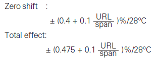
Overrange effect:
Zero shift, 0.3% of URL for any overrange to maximum limit.
Supply voltage effect:
Less than 0.05% of calibrated span per 10V.
Update rate:
60 msec
Step response:
Time constant: 0.08s (at 23°C)
Dead time: about 0.12s (without electrical damping)
Mounting position effect:
Zero shift, less than 0.1kPa {1mbar} for a 10° tilt in any plane. No effect on span. This error can be corrected by adjusting zero. (Double the effect for fluorinated fill sensors).
Dielectric strength:
500V AC, 50/60Hz 1 min., between circuit and earth.
Insulation resistance:
More than 100MΩ at 500V DC
Internal resistance for external field indicator:
12Ω or less.
Physical specifications
Electrical connections:
G1/2, 1/2-14 NPT, Pg13.5, or M20×1.5 conduit, as specified.
Process connections:
1/2-14NPT, Rc1/2, Rc1/4 or 1/4-18NPT, as specified.
Process-wetted parts material:

Non-wetted parts material:
- Electronics housing: Low copper die-cast aluminum alloy (standard), finished with polyester coating.
- Fill fluid: Silicone oil (standard) or fluorinated oil (Daifloil)
- Mounting bracket: 304 stainless steel
Environmental protection:
IEC IP67 and NEMA 6/6P
Mounting:
On 60.5mm (JIS 50A or 2B) pipe using mounting bracket, direct wall mounting, or direct process mounting.
Mass{weight}:
Transmitter approximately 2.2kg without options. Add; 0.5kg for mounting bracket.
Optional features
Indicator:
A plug-in turnable analog indicator (2.5% accuracy). An optional 5digits LCD meter with engineering unit is also available.
Local configurator with LCD display:
An optional 5 digits LCD meter with 3 push buttons can support items as using communication with FXW.
Arrester:
A built-in arrester protects the electronics from lightning surges. Lightning surge immunity: 4kV (1.2 x 50 μs).
Oxygen service:
Special cleaning procedures are followed throughout the process to maintain all process wetted parts oil-free. The fill fluid is fluorinated oil.
Degreasing:
Process-wetted parts are cleaned, but the fill fluid is standard silicone oil. Not for use for oxygen or chlorine measurement.
Optional tag plate:
An extra stainless steel tag with customer tag data is wired to the transmitter.
Accessories:
Hand-held communicator: (Model FXW, refer to Data Sheet No. EDS8-47)
FKH TYPE PRESSURE TRANSMITTERS FEATURES AND SPECIFICATIONS
The FCX–AIII absolute pressure transmitter (Direct mount type) accurately measures absolute pressure and transmits proportional 4 to 20mA signal. The transmitter utilizes the unique micromachined capacitive silicon sensor with state-of-the-art microprocessor technology to provide exceptional performance and functionality.Features
High accuracy
0.2% accuracy for all calibrated spans is the standard feature for all AP models covering 8.125 to 3000kPa {0.13 to 30bar} high pressure range. Fuji's micro-capacitance silicon sensor assures this feature for all suppressed calibration ranges without additional adjustment.
Minimum inventory
Electronics unit, communication module, local indicators and electronics housing are interchangeable among all FCX–AIII models.
Fuji/HART bilingual communication module
The communication module is "bilingual" to speak both Fuji proprietary protocol and HART. Any HART compatible devices can communicate with FCX–AIII series transmitters.
Application flexibility
Example features that render the FCX–AIII suitable for almost any process applications includes:
— Full range of hazardous location approvals
— Built-in RFI filter and lightning arrester
— 5-digits LCD meter
— The maximum span of each sensor can be converted to in different units using below factors.
Burnout current flexibility (Under Scale: 3.2 to 4.0mA, Over Scale: 20.0 to 22.5mA)
Burnout signal level is adjustable using Model FXW Hand Held Communicator (HHC) to comply with NAMUR NE43.
Functional specifications
Type:
4 to 20mA with digital signal
Service:
Liquid, gas, or vapor
Span, range, and overrange limit:
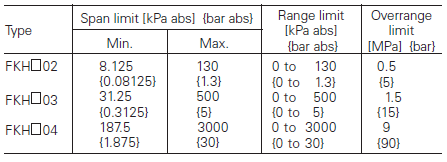
Output signal:
4 to 20mA DC with digital signal super- imposed on the 4 to 20mA signal.
Power supply:
Transmitter operates on 10.5V to 45V DC at transmitter terminals. 10.5V to 32V DC for the units with optional arrester.
Load limitations:
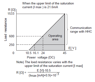
Note: For communication with FXW, min. of 250Ω required.
Zero/span adjustment:
Zero and span are adjustable either from the HHC. Zero is also adjustable externally from the adjustable screw.
Damping:
Adjustable electrical damping The time constant is adjustable between 0.06 to 32.0 seconds.
Zero elevation/suppression:
Zero may be elevated within the specified range limit of each sensor model.
Normal/reverse action:
Configurable from HHC.
Indication:
Analog indicator or 5-digit LCD meter, as specified.
Burnout direction:
Selectable from HHC. If self-diagnostic detect transmitter failure, the analog signal will be driven to either “Output Hold”, “Output Overscale” or “Output Underscale” modes.
- “Output Hold”: Output signal is hold as the value just before failure happens.
- “Output Overscale”: Adjustable within the range 20.0mA to 21.6mA from HHC. (Note: When the ambient temperature is -30°C or lower: 20.0mA to 20.8mA.)
- “Output Underscale”: Adjustable within the range 3.2mA to 4.0mA from HHC

Output Limits comforming the NAMUR NE43 by order.
Temperature limit:
- Ambient: −40 to +85°C
(−20 to +80°C for LCD indicator)
(−40 to +60°C for arrester option)
For explosionproof units (flameproof or intrinsic safety), ambient temperature must be within the limits specified by each standard.
- Process: −40 to +85°C for silicone fill sensor
- Storage: −40 to +90°C
Humidity limit:
0 to 100% RH
Communication:
With HHC (Model FXW, consult Data Sheet No. EDS8-47), following items can be remotely displayed or configured. Note: HHC’s version must be higher than 7.0 (or FXW _____1– _4), for FCX - AIII.
Local configurator with LCD display (option):
Local configurator with 3 push button and LCD display can support following items:
.png)
Performance specifications
Accuracy rating (including linearity, hysteresis, and repeatability):
For spans greater than 1/10 of URL: ±0.2% of span
For spans below 1/10 of URL:
Stability:
±0.2% of upper range limit (URL) for 10 years (In case of 6th digit code "3", "4")
Temperature effect:
Effect per 28°C change between the limits of −40°C and +85°C

Overrange effect:
Zero shift, 0.3% of URL for any overrange to maximum limit
Update rate:
60 msec
Step response:
Time constant. 0.08 s (at 23°C)
Dead time: about 0.12 s (without electrical damping)
Mounting position effect:
Zero shift, less than 0.1kPa for a 10° tilt in any plane. No effect on span. This error can be corrected by adjusting zero.
Dielectric strength:
500V AC, 50/60Hz 1 min., between circuit and earth.
Insulation resistance:
More than 100MΩ at 500V DC.
Internal resistance for external field indicator:
12Ω or less.
Physical specifications
Electrical connections:
G1/2, 1/2-14NPT, Pg13.5, or M20 x 1.5 conduit, as specified.
Process connections:
1/2-14 NPT, 1/4-18NPT, Rc1/2 or Rc1/4 as specified.
Process-wetted parts material:

Non-wetted parts material:
- Electronics housing: Low copper die-cast aluminum alloy (standard), finished with polyester coating, as specified.
- Fill fluid: Silicone oil.
- Mounting bracket: 304 stainless steel.
Environmental protection:
IEC IP67 and NEMA 4X
Mounting:
On 60.5mm (JIS 50A or 2B) pipe using mounting bracket, direct wall mounting, or direct process mounting.
Mass{weight}:
Transmitter approximately 2.2kg without options. Add; 0.5kg for mounting bracket.
Optional features
Indicator:
A plug-in turnable analog indicator (2.5% accuracy). An optional 5 digits LCD meter is also available.
Local configurator with LCD display:
An optional 5 digits LCD meter with 3 push buttons can support items as using communication with FXW.
Arrester:
A built-in arrester protects the electronics from lightning surges. Lightning surge immunity: 4KV (1.2×50μs).
Degreasing:
Process-wetted parts are cleaned, but the fill fluid is standard silicone oil. Not for use for oxygen or chlorine measurement.
Customer tag:
A stainless steel tag for customer tag data is wired to the transmitter.
Accessories:
Hand held communicator: (Model FXW, refer to Data Sheet No.EDS 8-47).


_series.png)
_series.png)
_series.png)
_series.png)
_series.png)
_series.png)
_soft_starters.png)


.png)


